")
The Hidden Pitfalls of Laboratory HVAC: Overlooked Areas That Threaten Compliance

A cleanroom can sail through its day-one ISO 14644 classification with pristine particle counts, balanced pressures, and validated airflow. Six months later, that same room can quietly drift out of compliance. Nothing dramatic announces the failure. Instead, dynamic airflow shifts, maintenance blind spots, and exhaust instability erode performance until a routine audit, or a contaminated batch reveals the problem.
This guide is written for facilities managers, cleanroom engineers, QA directors, and biotech operations leaders who already understand the basics and need to address the harder, often-ignored failure modes. You’ll learn where compliance erodes between qualification events, how to read the airflow dynamics that cause it, and which engineering decisions protect both product and energy budgets.
Before reading further, refer to the accompanying process flow diagram. It shows a typical laboratory airflow path – from the Air Handling Unit (AHU), through supply HEPA filtration, across cascading ISO-class lab zones, and out through the exhaust stack. More importantly, it identifies three key Risk Paths:
- Terminal HEPA Access,
- Transient Pressure Spikes,
- Exhaust/Fume Dynamics.
Each callout highlights a cross-contamination route that appears only when the system is under stress. I’ll return to these throughout the guide.
The Diagrammed Threat: Differential Pressure Cascades
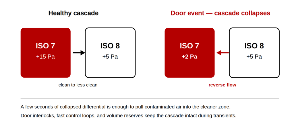
Look at the pressure gradient between zones in the diagram. In a healthy state, air moves from clean to less clean, and the cascade holds. The trouble starts when that cascade is challenged by real operational behavior, which is exactly what callout Transient Pressure Spikes illustrates.
Real Operational Dynamics vs. Steady-State Guidelines
Most cleanroom differential pressure guidelines are written for a steady state. Real labs are not steady. A door swinging open, a material airlock (MAL) cycling, or two adjacent doors opening at once can momentarily collapse the pressure differential. These events are briefly a few seconds – but they’re enough to reverse flow at a doorway and pull contaminated air into a cleaner zone. That’s the red risk path arrow in the diagram.
Key Engineering Contributors to Transient Pressure Control
Managing transient pressure drops in cleanrooms takes more than a higher static setpoint. Consider these contributors:
- Door interlocks and timing on airlocks so two barriers never open simultaneously.
- Fast-responding control loops tuned to recover pressure quickly without hunting or overshoot.
- Realistic volume reserves in the AHU to absorb sudden demand changes.
- Airflow visualization testing during commissioning that simulates door cycles, not just static balance.
The practical takeaway: pressure that looks perfect on a calm validation day can fail on a busy production shift. Test the dynamic behavior, not just the snapshot. For facilities under stricter pharmaceutical frameworks, cascade integrity matters even more – see how EU GMP Annex 1 grades map to ISO 14644 classes for the cleanroom you operate.
The Maintenance Trap: Overlooking Terminal Module Placement
Terminal HEPA Access in the diagram points to one of the most common and most underestimated sources of long-term failure. The issue isn’t the filter itself. It’s how the terminal modules and dampers were placed, and whether anyone can service them.
How Poor Accessibility Drives Long-Term Compliance Drift
Poorly located terminal HEPA housing creates a slow-burning problem. If a module sits above immovable equipment, behind ductwork, or in a corner with no clearance, cleanroom terminal HEPA filter maintenance becomes a project rather than a task. Filters that should be scanned and changed on schedule get deferred. Loading climbs, airflow drops, and the once-validated air change rate quietly falls below target.
The same logic applies to balancing dampers. When dampers are buried or undocumented, technicians can’t verify or adjust flow without disrupting the room. Over time, the system drifts and no one can confidently say why.
Proactive Strategies for Your Cleanroom HVAC Maintenance Checklist
A useful approach when reviewing a design or an existing facility:
- Confirm physical access to every terminal module and damper without removing fixed equipment.
- Map serviceability into your cleanroom HVAC maintenance checklist, not just filter part numbers.
- Document damper positions at validation so drift can be measured against a baseline.
- Schedule scan tests on a cadence the access allows.
A common mistake worth flagging treating filter replacement as the only maintenance event. In-situ leak scanning, gasket inspection, and damper verification matter just as much. Acceptance criteria and test methods should align with the ISO 14644-3 testing protocols. To put a monitoring and requalification cadence around that testing, see our ISO 14644-2 monitoring and requalification plan.
Exhaust Dynamics and Fume Management
Exhaust/Fume Dynamics in the diagram traces what happens when the exhaust side of the system falls out of balance with supply. Laboratory exhaust system design is where many otherwise-strong cleanrooms get into trouble, because exhaust is treated as an afterthought to supply.
The VAV Fume Hood Pressure Gap
Fume hoods are the usual culprits. A variable air volume (VAV) hood that ramps up sharply pulls a large, sudden volume of air. If the supply system can’t track that demand, room pressure dips and the cascade weaken. Preventing cross-contamination in lab exhaust depends on keeping supply and exhaust in lockstep, especially during these swings.
Critical Exhaust-Side Failure Modes to Monitor
Watch these exhaust-side failure modes:
- Supply lag rapid hood sash changes, causing pressure instability.
- Stack discharge re-entrainment, where exhausted air gets pulled back into nearby intakes.
- Shared exhaust manifolds allow one process to influence another.
- Inadequate face velocity at fume hoods when room balance shifts.
The relationship between supply balancing and exhaust capacity is the heart of stable operation. When you specify or audit a laboratory, model the worst-case simultaneous exhaust demand and confirm the supply can match it without sacrificing pressurization. Exhaust isn’t a passive outlet – it’s an active partner in containment.
Energy Recovery Without Risk: Advanced Engineering Solves the 100% OA Dilemma
Laboratories and cleanrooms frequently require 100% outdoor air (OA) for safety and contamination control. That requirement is expensive. Conditioning and filtering that much fresh air, then exhausting it, makes energy efficient cleanroom HVAC feel like a contradiction. It doesn’t have to be.
Balancing Thermal Efficiency and Cross-Contamination Safety
The dilemma is real: you can’t recirculate contaminated lab air, but you also can’t ignore the energy load of fully exhausting it. The engineering answer is energy recovery that never allows cross-contamination between exhaust and supply streams.
Several strategies help close the gap:
- Run-around glycol loops that transfer heat between exhaust and supply with zero air mixing.
- Membrane or coil-based recovery chosen specifically for non-cross-contaminating designs.
- Demand-based control, adjusting flow to occupancy and activity rather than running at peak around the clock.
- Right-sized air change rates, achieving cost-effective laboratory air change rates by matching ACH to actual cleanliness needs instead of over-designing.
The principle to protect at all costs: energy recovery must never become a contamination bridge. Any recovery device that risks leakage between streams defeats its own purpose. Select equipment validated for separation, and your energy savings won’t carry a compliance penalty. For broader context on design assumptions, the ASHRAE standards and guidelines are a useful reference point.
Frequently Asked Questions
Keep supply and exhaust airflow tightly coordinated so pressure cascades hold even during sudden demand changes, such as fume hood sash movements. Use non-cross-contaminating energy recovery, separate or carefully managed exhaust manifolds, and stack designs that prevent re-entrainment of discharged air into intakes. Validate the system under dynamic conditions, not just steady-state balance, so transient events don’t open a contamination path.
There’s no single universal number, appropriate differential pressure depends on your classification, layout, and regulatory framework, and is set during design and validation. As a general principle, air should always move from cleaner to less clean zones, with enough margin to survive transient events like door openings. Treat published ranges as typical project-dependent starting points and confirm your specific targets through qualified design and commissioning.
Inspection and integrity testing frequency varies with use, contamination load, and applicable standards, so it’s set by your validation and maintenance program rather than a fixed rule. The key is building scan-testing, gasket checks, and damper verification into a documented cleanroom HVAC maintenance checklist – and ensuring physical access supports that schedule. Filters in heavily loaded or higher-risk zones typically warrant more frequent attention.
Conclusion
Passing classification on day one proves a cleanroom can perform. Staying compliant proves it does. The gap between those two states lies in the overlooked areas your process flow diagram highlights: terminal HEPA access, transient pressure spikes, and exhaust dynamics. Each is a quiet risk path that only opens under real operational stress.
Start by stress-testing your pressure cascades dynamically, confirming maintenance access to every module, and balancing exhaust against worst-case demand. Then review your facility’s design against these three Risk Paths with us and prioritize the one that poses the greatest exposure to your operation.
GET IN TOUCH
Complete the form below to get in touch with our team.