")
The Science of Cleanroom Stabilization: Balancing Air Exchange Rates, Airlocks, and Humidity Controls

A standard commercial HVAC System is built for comfort. Clean rooms are built for control. That difference matters because a space that is acceptable for offices, retail, or light industrial use will fail quickly in a controlled environment where particle counts, pressure relationships, temperature, and moisture must stay within narrow operating bands.
For Facility Directors, Quality Assurance Managers, and Engineering Leads, the challenge is not simply cooling or heating a room. It is creating a stable environment where air handling, pressure cascades, filtration, and process conditions work together as one engineered system. In practical terms, that means hvac room design must support contamination control, personnel flow, material transfer, and compliance performance at the same time.
This article breaks down the core science behind cleanroom stabilization. You will learn how to evaluate the clean room air exchange rate, how a clean room airlock protects critical spaces, why cleanroom humidity requirements demand close control, and how the air handling unit serves as the mechanical core of the entire strategy.
The Blueprint for Air Exchanges: Calculating Volume and Rate
Air changes are one of the main levers that define cleanroom performance. The right clean room air exchange rate helps dilute and remove airborne particles, maintain temperature consistency, and support pressure control between adjacent spaces. The wrong rate can leave stagnant zones, increase contamination risk, and strain energy budgets without improving cleanliness.
Under widely recognized ISO 14644 regulatory frameworks, cleanliness classification is based on allowable airborne particle concentrations. While ISO classifications do not prescribe one universal air change number for every use case, engineering teams rely on established design ranges tied to ISO class targets, room geometry, occupancy load, and process sensitivity.
How to Calculate the Clean Room Air Exchange Rate
At its simplest, air changes per hour are calculated as:
ACH = Total Supply Airflow per Hour ÷ Room Volume
To convert airflow into a usable engineering basis:
- Measure room volume in cubic feet or cubic meters
- Determine supply airflow from the design fan capacity
- Multiply per-minute airflow by 60 to get hourly volume
- Divide hourly supply air by room volume
For example, if a room contains 10,000 cubic feet and the supply airflow is 5,000 cubic feet per minute, the room receives 300,000 cubic feet per hour. That results in 30 air changes per hour.
In real cleanroom practice, however, this calculation is only the starting point. Engineers also evaluate:
- ISO classification target
- Heat gain from equipment and lighting
- Occupancy density and gowning practice
- Filter loading and pressure drop
- Return air path design
- Ceiling coverage and diffuser layout
- Recovery time after door openings or process events
ISO Class Targets and Recommended ACH Ranges
Higher cleanliness classes need more aggressive air movement, tighter directional control, and more robust filtration. ISO Class 1 through ISO Class 5 environments often depend on unidirectional airflow strategies, while ISO Class 6 through ISO Class 8 spaces often use mixed or turbulent flow with carefully managed dilution.
General design expectations often follow this pattern:
- ISO Class 1–4: Typically require highly controlled unidirectional airflow, often defined more by face velocity than by ACH alone
- ISO Class 5: Commonly designed around high-volume air delivery with substantial HEPA-filtered ceiling coverage
- ISO Class 6: Requires strong dilution and consistent recirculation
- ISO Class 7: Often falls into a moderate-to-high ACH design range depending on occupancy and process criticality
- ISO Class 8: Usually supports lower ACH than tighter classifications but still exceeds standard commercial practice by a wide margin
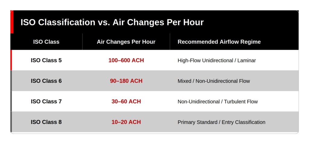
Caption: Technical data table illustrating recommended air exchange rate ranges for common cleanroom classifications, including ISO Class 5 at approximately 240–600 ACH, ISO Class 6 at approximately 90–180 ACH, ISO Class 7 at approximately 30–60 ACH, and ISO Class 8 at approximately 10–25 ACH, depending on process load, occupancy, recovery expectations, and filter layout.
Why HVAC Air Exchange Velocity Matters
The volume of air is important, but the velocity of hvac air exchange is equally important. If air moves too slowly, particles can remain suspended or settle in critical zones. If velocity is too high, turbulence may re-entrain contaminants and disrupt process stability.
This is where engineered diffuser placement, return grille positioning, and supply uniformity become essential. In high-performance clean rooms, airflow must do three things at once:
- Sweep contaminants away from the process
- Avoid dead spots and eddies
- Support stable pressure relationships across adjacent spaces
That level of control requires more than standard duct balancing. It often demands specialized ceiling layouts, controlled recirculation paths, and custom HVAC supply and installation solutions tailored to the room’s classification and process load.
Managing Pressure Cascades: The Role of Airlock Infrastructure
Air exchange removes contaminants, but pressure control keeps them from entering in the first place. That is why a cleanroom cannot rely on filtration alone. It also needs a pressure cascade that protects the most critical space from surrounding areas during personnel entry, material transfer, and door cycling.
A properly designed clean room airlock acts as a buffer zone. It separates classified and unclassified spaces while reducing the contamination risk associated with movement between them. In a well-planned airlock cleanroom sequence, the airlock is not just a vestibule. It is an active contamination-control component embedded into the overall hvac system design.
How Pressure Cascades Protect the Critical Core
Most cleanroom environments use positive pressure when the goal is to keep outside contamination from entering. In that configuration, the cleanest room is maintained at the highest pressure, and adjacent spaces step down gradually.
This staged differential helps ensure airflow moves outward from cleaner areas to less clean areas. The result is a directional barrier that limits infiltration when doors open briefly.
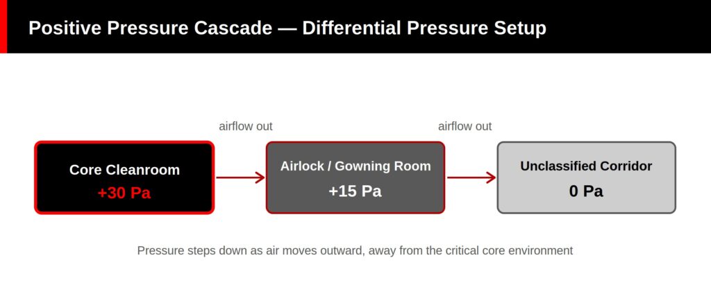
Flowchart description: Airflow moves from the high-pressure critical core at +30 Pa into the airlock or gowning room at +15 Pa, then outward to the unclassified corridor at 0 Pa. The diagram shows directional arrows at each door opening, illustrating how pressure differentials maintain outward airflow and protect the clean core during entry and exit events.
Negative pressure cascades are used in other cases, such as containment applications where hazardous materials must remain isolated. In either case, the design objective is the same: maintain directional airflow based on process risk.
Designing the Clean Room Airlock for Performance
A high-functioning clean room airlock depends on more than setpoints on a control screen. It requires coordinated room geometry, door interlocks, airflow offset, and responsive controls. Effective airlock design typically includes:
- Pressure differential setpoints between adjacent rooms
- Door sequencing to avoid simultaneous openings
- Supply and exhaust balancing for stable offset
- Finishes and joints that support cleaning protocols
- Personnel and material segregation where needed
The envelope matters too. Pressure stability is hard to maintain if leakage occurs at wall transitions, ceilings, or service penetrations. That is why pressure cascade strategies are often paired with modular wall and containment systems that support tight construction tolerances and repeatable performance.
Humidity & Micro-Climate Control: Deconstructing Regulatory Standards
Many facilities focus first on particles and pressure, but moisture control is just as critical. Poor humidity control can compromise product quality, increase static events, trigger condensation, and create conditions that support microbial growth. In pharmaceutical, biotechnology, semiconductor, and precision manufacturing environments, that can translate directly into batch loss, yield reduction, or compliance findings.
Cleanroom humidity requirements therefore sit at the center of environmental control strategy. They are not just comfort settings. They are process protection settings.
Why Clean Room Humidity Standards Matter
The right humidity range depends on the process, materials, and regulatory context. Semiconductor operations may prioritize electrostatic discharge prevention. Pharmaceutical and sterile environments may focus on microbial risk, material integrity, and operator comfort under gowning conditions.
Common consequences of poor moisture control include:
- High humidity
- Condensation on surfaces or equipment
- Greater microbial survivability in some conditions
- Material degradation and packaging instability
- Low humidity
- Electrostatic discharge events
- Product handling issues
- Operator discomfort and increased particle shedding
Because of these risks, clean room humidity standards are often set as part of a broader environmental monitoring and compliance framework.
Understanding ISO 14644 Humidity Requirements in Practice
Strictly speaking, iso 14644 humidity requirements are not expressed as a single universal humidity percentage for all cleanrooms. ISO 14644 focuses primarily on airborne particulate cleanliness and cleanroom operations. In practice, humidity setpoints are established through user requirements, process demands, and related regulatory expectations.
That distinction is important. When engineering teams discuss iso 14644 humidity requirements, they are often referring to humidity control expectations within an ISO-classified room rather than a universal ISO-mandated RH threshold.
Typical operational ranges may fall around 30% to 60% relative humidity, but critical processes may narrow that significantly. Design teams should align humidity strategy with:
- Product sensitivity
- Static discharge risk
- Microbial control objectives
- Temperature setpoints
- Occupancy and gowning loads
- Applicable USP standards or FDA GMP guidelines
The Control Layer: Sensors, Alarms, and Trending
Maintaining humidity is not only about dehumidification or humidification capacity. It is also about response speed, calibration accuracy, and alarm logic. Sensors must be placed correctly, integrated into the controls architecture, and verified against operational reality.
For many facilities, the difference between passing and failing an environmental trend review comes down to the quality of the monitoring layer. Integrated monitoring systems, control, and automation help facilities track RH drift, identify excursions early, and connect alarms to root causes such as valve failure, coil fouling, or door management issues.
Advanced HVAC System Integration: The Air Handling Core
At the center of cleanroom stabilization is the air handling unit. This is where filtration, temperature control, humidity conditioning, and airflow delivery come together into one integrated operating system. In controlled environments, the AHU is not a background utility. It is the mechanical core that makes the room perform as intended.
How the Air Handling Unit Supports Cleanroom Stability
An industrial air handling unit conditions incoming and recirculated air before delivering it to the clean space. Depending on the application, that may include:
- Pre-filtration and final filtration stages
- Cooling and heating coils
- Humidification or dehumidification components
- Supply fans with variable speed control
- Outside air and return air mixing sections
- Differential pressure monitoring across filters and coils
Effective air handling design balances cleanliness, energy use, and control precision. In many cleanroom applications, a significant portion of supply air is recirculated through high-efficiency filtration to maintain required particle performance while limiting energy waste.

Diagram description: Schematic showing conditioned supply air leaving the AHU, passing through terminal or ceiling-mounted HEPA filters, entering the cleanroom in a controlled airflow pattern, then traveling downward and across the space to low-wall return air grilles. Return air flows back to the recirculation path, where it is reconditioned in the AHU before being supplied again.
Why Integration Matters More Than Individual Components
A cleanroom does not perform well because one component is oversized or high spec. It performs well because all components are tuned to the same control objective. The fan curve, filter resistance, duct static pressure, room leakage, pressure offsets, and control sequence must all work together.
That integration challenge is where many projects struggle. A room may have adequate filtration but unstable pressure. It may hit temperature targets but miss RH tolerance. It may achieve startup certification and then drift during normal operations. The solution is not isolated equipment selection. It is coordinated engineering, commissioning, and lifecycle optimization.
A typical ISO Class 7 cleanroom is often designed in the range of about 30 to 60 air changes per hour. The exact clean room air exchange rate depends on occupancy, process sensitivity, heat load, and recovery requirements.
A clean room airlock prevents cross-contamination by creating a controlled transition zone between spaces with different cleanliness levels or pressure conditions. By maintaining directional airflow and staged pressure differentials, the airlock cleanroom arrangement reduces the chance that particles will move into the critical core during entry or material transfer.
Relative cleanroom humidity requirements are tightly controlled because humidity affects product stability, microbial risk, operator conditions, and static discharge potential. While iso 14644 humidity requirements are often defined through process and facility specifications rather than one universal RH rule, strict control is essential for maintaining validated and repeatable operating conditions.
Conclusion: Why End-to-End Engineering Matters
Cleanroom stabilization depends on balance. The HVAC System must deliver the right air volume, the right airflow pattern, the right pressure relationships, and the right humidity control at the same time. If one variable drifts, the whole environment becomes harder to validate, harder to operate, and harder to protect.
That is why many facilities need more than equipment procurement. They need an engineering partner that can align process requirements, room envelope strategy, air handling performance, controls integration, and compliance expectations into one coordinated design. ACH Engineering serves as that end-to-end partner through Turnkey Cleanroom Solutions, HVAC Supply & Installation, and Control and Automation Systems.
To review your facility specifications, optimize your HVAC System layout, or discuss a new controlled environment project, connect with the cleanroom design and project management specialists at achengineering.com.
GET IN TOUCH
Complete the form below to get in touch with our team.