

Cleanroom Plenum Design Consideration Guidelines: Optimizing Airflow and Enclosures

The cleanroom ceiling plenum is not an afterthought. It acts as a vital component of your contamination control strategy. The cavity above the cleanroom ceiling grid serves as a housing area for various utilities while simultaneously acting as the distribution space for FFU cleanroom (fan filter unit) modules and filter banks to achieve required environmental parameters within process areas. Get the cleanroom plenum design wrong and every downstream system suffers: uneven airflow, particle count failures, pressure cascade breakdowns, and validation delays that push commissioning timelines out by weeks or months.
Whether you are designing a pharmaceutical cleanroom, a sub-micron semiconductor cleanroom, or a complete modular cleanroom room system, this guide covers the engineering decisions that determine whether a cleanroom plenum performs to specification. We examine everything from cleanroom HVAC system integration and materials of construction to negative vs. positive pressurization, cleanroom HEPA filter placement, and a load bearing cleanroom ceiling structure.
For a broader overview of what to expect before cleanroom construction begins, review ACH Engineering’s comprehensive modular cleanroom design guidelines and cleanroom planning guide.
Integrating the Cleanroom HVAC System with Plenum Architecture
The plenum room or plenum area is designed to contain and convey conditioned air into the cleanroom space. Plenums may operate under positive pressure or negative pressure relative to the cleanroom area.
Materials of Construction for Cleanroom Plenums
The materials chosen for plenum construction impact particle shedding, containment, and structural performance. Common material options include:
- Sheet Metal: Galvanized, powder-coated, or epoxy-coated steel and aluminum.
- Double-Wall Panels: Double-wall metal honeycomb cleanroom wall/ceiling panels. Explore ACH Engineering’s modular wall and ceiling panel options.
- Sheetrock / Drywall: Treated and sealed to strictly prevent particle shedding into the airflow path.
Selection criteria must weigh contamination control requirements, fire ratings, constructability, ease of future alterations, and overall capital cost.
Open Pressurized Plenums vs. Ducted Air Distribution Systems
Two primary configurations dominate cleanroom plenum design: open pressurized plenums and fully ducted air distribution systems. Each carries distinct implications for static pressure management, filter coverage, and maintenance access.
Open Pressurized Plenum
- The plenum area is maintained at positive or negative pressure relative to the cleanroom below based on process demands.
- Conditioned supply air floods the plenum cavity and distributes through an FFU cleanroom (fan filter unit) matrix or terminal cleanroom HEPA filter units across the cleanroom ceiling grid.
- Pressure equalization is managed by the Air Handling Unit (AHU) static pressure output.
- Filter coverage is flexible – FFUs can be repositioned without duct modification.
- Preferred in a flexible modular cleanroom where future reconfiguration is anticipated.
Ducted Air Distribution System
- Supply air and return air are channeled through fixed ductwork to discrete discharge points.
- Offers precise directional control but limits layout flexibility.
- Preferred where supply volume to individual zones must be independently balanced.
- Higher fabrication and installation cost; duct penetrations introduce additional sealing requirements during cleanroom construction.
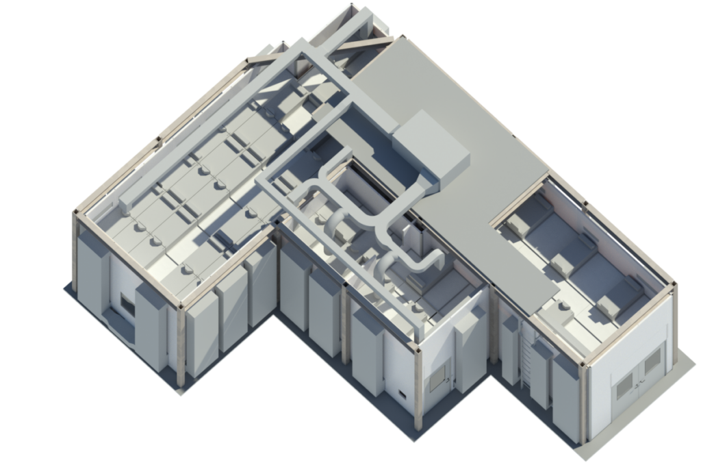
In larger plenum room applications, many mechanical engineers implement a ducted supply distribution approach where main duct branches penetrate the top of the plenum at multiple locations. This ensures conditioned air from the cleanroom HVAC system is distributed evenly across the upper boundary before reaching the filter plane. Pharmaceutical cleanroom
suites with stringent cGMP zoning often favor ducted configurations, whereas a modular cleanroom system for electronics or medical devices frequently utilizes pressurized open plenums for adaptability.
Pressurization Requirements Inside the Plenum
Understanding cleanroom positive vs negative pressure relationships within the plenum cavity is critical for operational stability.
Negative Pressurization Plenums
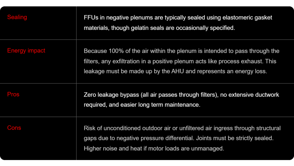
When utilizing fan filter units (FFUs), the plenum area is typically under negative pressure relative to the cleanroom process area and the outdoors. Negative plenums ensure all air is pulled actively through the FFUs and their filtration media.
Positive Pressurization Plenums
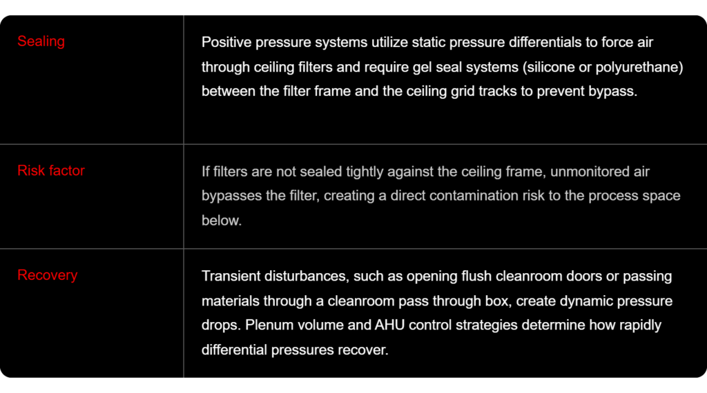
In a positive pressurized plenum, the cavity pressure is higher than the cleanroom process area and the outdoors.
Achieving ACPH and ISO Class Targets
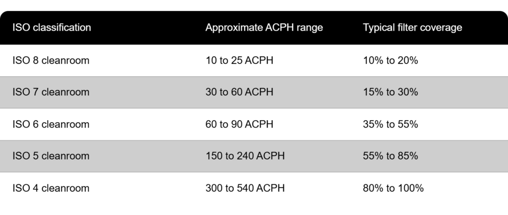
Achieving target airchanges per hour (acph) is a core concern for cleanliness and contamination dilution. While ACPH alone is not the sole factor in certifying an ISO class, it serves as the essential calculation to achieve required particle count thresholds.
Per ISO 14644-1 Cleanroom Standards, target ACPH aligns with room classification:
Cost-Effective ACPH Strategy: Target ACPH metrics can often be achieved more cost-effectively through precise cleanroom plenum design and FFU arrangement rather than relying on extensive ductwork. This strategy reduces total reliance on central Air Handling Units for air turnover. Increasing filter coverage at a fixed AHU capacity increases effective ACPH by passing the air volume through greater surface area at lower face velocities.
Air Filtration Dynamics: FFU and HEPA Filter Layouts
Filtration delivers the core function of the cleanroom plenum: controlled, particle-reduced air.
Air Pathways & Internal Plenum Geometry
Supply air enters the plenum room from the cleanroom HVAC system conditioned for temperature, humidity, and static pressure and spreads laterally across the cavity. Plenum depth and geometry must allow pressure equalization before air hits the filter plane.
A primary point of failure is insufficient plenum depth relative to diffuser throw distance. High-velocity air entering from diffusers impinges on the cleanroom ceiling grid before equalizing, causing localized high-velocity zones and low-velocity starved areas. Recommended minimum plenum depths range from 18 to 24 inches, with deeper cavities needed for dense FFU arrays.
FFU Layouts Acting with Terminal HEPA Matrices
- FFU Cleanroom Systems: FFU cleanroom (fan filter unit) modules house EC motor-driven fans with cleanroom HEPA filter or ULPA media. Drawing from the pressurized plenum, they operate in parallel to ensure airflow uniformity.
- Terminal HEPA Filters: Passive units relying entirely on AHU static pressure, typically paired with ducted supply systems.
Key FFU Design Parameters
- Coverage Percentage: 15-30% for ISO 7 cleanroom, up to 80-100% for ISO 5 cleanroom or unidirectional Grade A zones.
- Face Velocity: Target face velocities range between 0.36 to 0.54 m/s (70-105 fpm) for unidirectional airflow.
- Module Spacing: Grid layouts must eliminate gap zones to prevent unfiltered plenum air from bypassing filtration and re-entraining into clean space.
Structural Integrity: Load Bearing Cleanroom Ceiling Grids
The cleanroom ceiling grid must handle both dead loads and live loads without structural deflection. Structural sagging breaks filter seals, causes bypass leaks, and leads to costly facility shutdowns.
- Dead Loads: FFUs (35-55 lbs/unit), terminal HEPA housings (20-40 lbs/unit), lighting, utility piping, and conduit.
- Live Loads: Maintenance personnel access. A load bearing cleanroom ceiling (walkable ceiling) is engineered to sustain 250-300 lbs per 4 sq. ft., enabling technicians to service the plenum area directly without damaging room seal integrity.
Turnkey Cleanroom Construction & Validation Compliance
Designing a cleanroom plenum requires integrating HVAC design, architectural panel systems, and filtration mechanics. Procurement fragmentation-buying the cleanroom HVAC system from one vendor, ceiling grids from a second, and panels from a third-creates interface gaps, pressure drops, and sealing failures.
Turnkey Integration Advantages with ACH Engineering
- Coordinated Engineering: Static pressure calculations, plenum depth, and cleanroom flooring integration are developed under a single scope.
- Single-Source Fabrication: Wall panels, walkable ceiling grids, and HVAC components are manufactured to matching tolerances.
- Streamlined IQ/OQ/PQ: Filter integrity testing DOP/PAO challenge testing per IEST-RP-CC034 and validation compliance are managed smoothly. Explore ACH Engineering’s cleanroom validation support services for full details.
Contact ACH Engineering today to consult with our engineering team on optimizing your cleanroom plenum design.
Frequently Asked Questions
What is the purpose of the plenum in a cleanroom?
The cleanroom plenum is a pressurized cavity located above the ceiling grid. It receives conditioned air from the cleanroom HVAC system and distributes it through FFUs or terminal cleanroom HEPA filter units into the room below to maintain pressure, velocity, and ISO compliance.
What is the difference between an open pressurized plenum and a ducted plenum?
An open pressurized plenum floods the above-ceiling space with air, allowing FFUs to draw from a common pressurized volume. A ducted plenum uses fixed ductwork to channel air directly to specific ceiling points for tight zone-by-zone control.
What ceiling filter coverage percentage is required for ISO Class 5?
An ISO 5 cleanroom typically requires 25% to 80% filter coverage (and up to 100% for unidirectional flow zones) to sustain strict ACPH and particle count limits.
How does negative vs. positive pressurization impact plenum performance?
A negative plenum draws air inward through FFUs, preventing unfiltered bypass into the cleanroom, but requires proper panel sealing to prevent unconditioned outdoor air leaks. A positive plenum forces air down through filters, requiring gel-seal systems to prevent air from bypassing the filter frame.
GET IN TOUCH
Complete the form below to get in touch with our team.