Introduction: Why Cleanroom Standards Matter in PCB Assembly
Why Cleanroom Standards Matter in PCB Assembly
A single dust particle—as small as 10 microns—can destroy a PCB assembly, triggering product failures or costly safety recalls. As HDI boards shrink and fine-pitch components like 01005 and 0201 become standard, microscopic contamination becomes exponentially more dangerous.
Particle defects account for up to 75% of all defects in high-density electronics manufacturing. That's why PCB facilities now require contamination control once reserved for semiconductor fabs.
This guide breaks down what those controls actually look like in practice — ISO classifications, environmental requirements, ESD protocols, and cleanroom construction approaches that protect your assemblies and your production yield.
Understanding ISO Cleanroom Classifications for PCB Assembly
The ISO 14644-1 Standard Explained
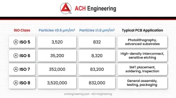
ISO 14644-1:2015 defines cleanroom air cleanliness by maximum allowable particle concentration per cubic meter. For PCB assembly, relevant classes range from ISO Class 5 (critical processes) to ISO Class 8 (general assembly).
Key Classifications for PCB Manufacturing:
| ISO Class | Particles ≥0.5 µm/m³ | Particles ≥1.0 µm/m³ | Typical PCB Application |
|---|---|---|---|
| ISO 5 | 3,520 | 832 | Photolithography, advanced substrates |
| ISO 6 | 35,200 | 8,320 | Fine-pitch assembly, flexible circuits |
| ISO 7 | 352,000 | 83,200 | Standard SMT assembly |
| ISO 8 | 3,520,000 | 832,000 | General assembly areas |
Matching ISO Class to Your PCB Products
Standard SMT Assembly (ISO Class 7 or 8): General surface mount lines typically operate in ISO Class 7 environments to control particles that could block stencil apertures or contaminate solder paste. This classification prevents macro-particle contamination while remaining cost-effective for high-volume production.
Fine-Pitch Components and CSP/BGA (ISO Class 6): As component sizes shrink to 01005 or 0201 packages, tolerance for particle contamination decreases sharply. ISO Class 6 prevents defects in ultra-fine pitch printing where particles cause bridging or insufficient paste transfer.
Photolithography and Imaging (ISO Class 5 or 6): A single dust particle can disrupt pattern transfer for fine-line circuitry, causing shorts or opens. Facilities performing photolithography must maintain Class 5 or 6 conditions to protect bare boards during exposure and development.
Impact on Yield and ROI
Upgrading environmental controls has measurable payoff: industry case studies report yield improvements of 12–18% after tightening cleanroom classification. In one documented example, a semiconductor facility saw a 14% yield increase after transitioning to ISO Class 5 conditions.
Common Defect Mechanisms:
- SMT printing: particles block stencil apertures, causing insufficient solder deposits or bridging between fine-pitch pads
- Photolithography: particles on photoresist act as masks, creating unwanted copper (shorts) or missing copper (opens)
- Reflow: contaminants trapped in solder paste volatilize during reflow, causing voids or component tombstoning
Decision Framework for Classification Selection
These yield risks make classification selection a direct business decision — not just a compliance exercise. Start by assessing your process characteristics:
Assess these factors:
- Minimum line width and spacing on your PCBs
- Smallest component pitch in your assembly process
- Substrate type (rigid FR-4, flexible polyimide, advanced materials)
- Customer quality requirements and industry standards
Upgrade to higher classification when:
- Component pitch drops below 0.4mm
- Line widths approach 50 µm or less
- Yield losses exceed 2-3% due to contamination-related defects
- Customer specifications mandate tighter controls
Critical Environmental Controls: Temperature, Humidity, and Pressure
Temperature Stability Requirements
Precise temperature control maintains material performance throughout PCB assembly. Each process stage has its own tolerance band — drift outside those bands and defects follow quickly.
| Process | Target Range | Why It Matters |
|---|---|---|
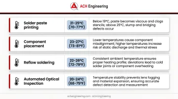
| Solder paste printing | 21–25°C (70–77°F) | Below 19°C, paste becomes viscous and clogs stencils; above 25°C, slumping and bridging occur |
| Photoresist coating/exposure | 20–22°C ±1°C | Variations outside ±1°C compromise film thickness, adhesion, and pattern resolution |
| FR-4 substrate handling | Stable (minimize swings) | CTE of ~14 ppm/°C means temperature shifts cause dimensional drift and registration errors in fine-pitch assembly |
Humidity Control by Process Type
Humidity control balances ESD risk against moisture-related defects. Too dry and static discharge becomes a real threat; too humid and boards absorb moisture that degrades performance.
Key humidity targets by process area:
- General assembly (40–60% RH): Prevents ESD events while limiting moisture absorption in PCBs and components
- Photolithography (30–50% RH, optimal ~43%): High humidity (>60%) causes condensation on resist; below 30%, resist sensitivity and development rates drop
- All metal-exposed surfaces: Stay below 60% RH — ionic contamination combined with high humidity accelerates electrochemical migration and corrosion
Pressure Differentials and Air Change Rates
Maintain 10–15 Pascals (Pa) positive pressure differential between clean zones and adjacent less-clean areas. This prevents contaminant infiltration from adjacent spaces. Each successive zone should maintain higher pressure than the next less-clean area — a cascade approach that keeps particulates moving outward, not inward.
Air Change Rates by Classification:
| ISO Class | Air Changes per Hour | Airflow Pattern |
|-----------|---------------------|-----------------|
| ISO 5 | 240-600+ | Unidirectional (laminar) |
| ISO 6 | 70-160 | Mixed/non-unidirectional |
| ISO 7 | 30-60 | Non-unidirectional |
| ISO 8 | 10-25 | Non-unidirectional |
Higher air change rates dilute and remove particles more effectively, but they also drive up energy costs significantly. Over-specifying your ISO class to add a buffer can double HVAC operating expenses — match your ACR to the classification your process actually requires.
Monitoring and Documentation
Consistent monitoring is what turns environmental targets into verified compliance. At minimum, your system should track:
Essential monitoring parameters:
- Temperature: Continuous monitoring with ±0.5°C accuracy
- Humidity: Continuous monitoring with ±3% RH accuracy
- Pressure differentials: Continuous monitoring with visual indicators
- Air velocity: Quarterly verification for laminar flow zones
Sensors drift over time, so calibration schedules matter as much as the monitoring itself:
Calibration schedules:
- Temperature sensors: Annual calibration
- Humidity sensors: Semi-annual calibration
- Pressure sensors: Annual calibration
- Particle counters: Annual calibration
Retain all records with timestamps and technician sign-off. Most quality management systems and regulatory audits require a minimum two-year lookback — build that into your documentation protocol from day one.
Contamination Control Systems and Best Practices
Three Primary Contamination Sources
Three sources account for the vast majority of cleanroom contamination in PCB assembly environments:
- Personnel — Operators shed millions of particles per minute through skin flakes, hair, clothing fibers, and oils. Movement amplifies this through turbulent air dispersion.
- Materials — PCB substrates carry dust, fibers, and epoxy shavings from routing. Cardboard packaging is a major particle generator and should never enter the cleanroom.
- Processes — Solder fumes, flux residues, and equipment wear (belts, bearings) create internal contamination. Etching and other chemical processes release vapors and particulates.
Personnel Protocols
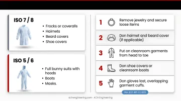
Gowning requirements follow IEST-RP-CC003 and scale with ISO classification:
- ISO 7/8 environments: Frocks or coveralls, hairnets, beard covers, shoe covers
- ISO 5/6 areas: Full bunny suits with hoods, boots, and masks
Proper gowning sequence:
- Remove jewelry and secure loose items
- Don hairnet and beard cover (if applicable)
- Put on cleanroom garments from head to toe
- Don shoe covers or cleanroom boots
- Don gloves last, overlapping garment cuffs
Training requirements:
- Initial gowning training with competency verification
- Proper cleanroom behavior (slow, deliberate movements)
- Contamination awareness and prevention
- Annual refresher training
Air showers at entry points require 15–30 second cycles to dislodge loose particles from garments before personnel enter the controlled area.
Material Transfer Protocols
Pass-through chambers between zones are the correct method for material transfer. Wipe down all items before placing them in the pass-through, and never open both doors at once — doing so destroys the pressure differential between zones.
Packaging requirements:
- Remove cardboard and wood pallets before cleanroom entry
- Use only cleanroom-compatible packaging materials
- Vacuum-sealed bags for sensitive components
- Antistatic packaging for ESD-sensitive devices
Clean bare PCB boards before printing using contact cleaning (tacky rollers) or vacuum methods. Removing debris at this stage directly improves solder print yield.
Process-Specific Controls
Each major process in PCB assembly requires its own contamination containment approach:
- Soldering — Install fume extraction directly at soldering points; use HEPA-filtered exhaust to prevent particle recirculation back into the workspace.
- Etching — Contain chemical processes in dedicated areas with separate exhaust systems and proper waste management to prevent cross-contamination.
- Chemical handling — Use closed-loop chemical delivery systems. Store bulk chemicals in dedicated areas outside the cleanroom.
Electrostatic Discharge (ESD) Control
Contamination control and ESD control are inseparable in PCB assembly — a single uncontrolled discharge can destroy components that survived every other handling step.
Essential ESD measures:
- Conductive flooring: Resistance-to-ground between 1.0 x 10⁶ and 1.0 x 10⁹ ohms
- Wrist straps: Test continuity daily; maintain resistance < 3.5 x 10⁷ ohms
- Ionizing air bars: Maintain balance (offset voltage) < ±50V (±35V for sensitive devices)
- Humidity management: Keep RH > 30% to facilitate charge dissipation
- Grounding: Ground all equipment, workstations, and conductive surfaces
ESD programs should meet ANSI/ESD S20.20 (North America) or IEC 61340-5-1 (International) requirements. Both standards specify testing frequencies, equipment specs, and audit protocols.
Air Filtration and HEPA Systems
Filter Efficiency Specifications
The two primary filter types used in PCB assembly cleanrooms differ in capture efficiency and application range:
| Filter Type | Efficiency | Particle Size | Typical ISO Classes |
|---|---|---|---|
| HEPA (High Efficiency Particulate Air) | 99.97% | 0.3 µm | ISO Class 5–8 |
| ULPA (Ultra Low Particulate Air) | 99.999% | 0.12 µm | ISO Class 4 and better |
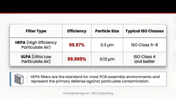
HEPA filters are the standard for most PCB assembly environments and represent the primary defense against airborne contamination. ULPA filters are reserved for processes requiring maximum particle removal, such as critical photolithography steps. Both must meet ISO 29463 and EN 1822 classifications, which test efficiency at the Most Penetrating Particle Size (MPPS).
Airflow Patterns
Unidirectional (Laminar) Flow: Air flows in parallel lines at a uniform velocity of 0.3–0.5 m/s, sweeping particles away from products either vertically or horizontally. This pattern is essential for ISO Class 5 zones such as photolithography and wafer handling.
Non-Unidirectional (Turbulent) Flow: Air mixes and dilutes contamination through turbulent diffusion rather than directional sweeping. This approach suits ISO Class 7 and 8 general assembly areas and is more energy-efficient than laminar flow, making it the practical choice where absolute particle removal is less critical.
Filter Testing and Replacement
Integrity testing uses an aerosol challenge (such as PAO) combined with photometer scanning. Leaks must not exceed 0.01% of upstream concentration at any point.
Testing frequency:
- ISO Class 5 environments: Every 6 months
- ISO Class > 5 environments: Every 12 months
- After filter replacement: Immediate integrity testing before resuming operations
Replacement schedules: HEPA filters typically last 1-2 years depending on usage and environmental conditions. Replace when:
- Pressure differential exceeds manufacturer specifications
- Particle counts fail to meet classification requirements
- Integrity testing reveals leaks exceeding 0.01%
- Visual inspection shows damage or deterioration
Monitoring filter performance: Install differential pressure gauges across filter banks. Rising pressure differential indicates filter loading and signals an approaching replacement need — addressing this proactively prevents particle count excursions that could jeopardize ISO classification compliance.
Modular vs. Traditional Cleanroom Construction for PCB Facilities
Construction Timeline Comparison
Modular cleanrooms: Complete installation in 8–16 weeks from design to operation. Design takes just 2–3 weeks, followed by offsite manufacturing and 4–8 weeks of onsite assembly.
Traditional stick-built construction: Requires 6–12 months from design through completion. Extended timelines stem from sequential construction phases, custom fabrication, and multi-trade coordination.
Impact on production: Modular construction minimizes production downtime—critical for PCB manufacturers where every week of facility unavailability represents significant lost revenue.
Flexibility and Reconfiguration Advantages
Modular systems give electronics manufacturers options that traditional construction simply can't match:
- Expand by adding sections without demolishing existing structures
- Reconfigure layouts, add airlocks, or resize rooms with minimal disruption
- Disassemble and relocate cleanrooms to different facilities as operations shift
- Upgrade ISO classification by enhancing filtration and environmental controls
That adaptability directly affects the bottom line — which is where the cost comparison becomes compelling.
Cost Comparison and ROI
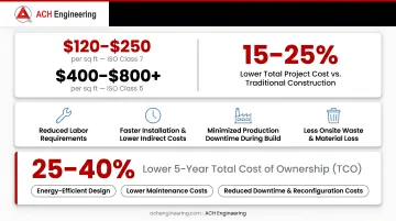
Modular cleanroom materials typically run $120–$250 per square foot for ISO Class 7, or $400–$800+ for ISO Class 5. Material costs are broadly comparable to traditional construction, but total project costs run 15–25% lower due to:
- Reduced labor requirements
- Faster installation with lower indirect costs
- Minimized production downtime during build
- Less onsite waste and material loss
Over five years, modular cleanrooms deliver 25–40% lower total cost of ownership (TCO):
- Energy-efficient designs with optimized airflow cut operating costs
- Reduced maintenance requirements compared to traditional builds
- Lower reconfiguration costs when production needs change
- Retained salvage value if the cleanroom is relocated or repurposed
ACH Engineering's Modular Approach
ACH Engineering designs and builds modular cleanroom solutions specifically suited to electronics manufacturing environments. Their prefabricated systems deliver:
- Components manufactured in factory-controlled conditions for consistent quality
- Turnkey project delivery from design through commissioning
- ISO Class 1–9 compliance covering all PCB assembly classifications
- ESD-safe configurations built for semiconductor and electronics applications
- 8–12 week total deployment timelines to minimize production disruption
ACH Engineering's modular approach includes HEPA filtration systems, controlled pressurization, and precise environmental controls (18–24°C temperature, 30–60% humidity) specifically tailored to PCB assembly requirements.
Cleanroom Maintenance and Compliance
Cleaning Protocols
Daily cleaning:
- Wipe down all horizontal surfaces with cleanroom-compatible cleaning agents
- Vacuum floors using HEPA-filtered vacuum systems
- Remove waste and replace cleanroom garments
Weekly cleaning:
- Clean walls and partitions with approved cleaners
- Sanitize pass-through chambers and airlocks
- Clean and inspect air grilles and diffusers
Monthly cleaning:
- Deep clean floors with approved cleaning systems
- Clean light fixtures and ceiling surfaces
- Inspect and clean equipment surfaces
Approved cleaning agents:
- Use ESD-safe cleaners that leave no residues and generate minimal particles
- Isopropyl alcohol (IPA) and designed solvents are standard choices
- Follow IEST-RP-CC018 guidelines, which govern cleanroom cleaning processes and agent selection
Testing and Certification Requirements
Particle counting:
- ISO Class ≤5: Every 6 months
- ISO Class >5: Every 12 months
- Test at-rest and operational states
- Document particle concentrations at multiple locations
HEPA filter leak testing:
- ISO Class ≤5: Every 6 months
- ISO Class >5: Every 12 months
- Scan entire filter face for leaks
- Verify leakage < 0.01% of upstream concentration
Air velocity and volume measurements:
- Verify air change rates meet specifications
- Measure velocity in laminar flow zones
- Test semi-annually for critical areas
Pressure differential monitoring:
- Continuous monitoring with visual indicators
- Document readings daily
- Investigate immediately if differentials fall below specifications
All test data from these checks feeds directly into your compliance documentation — which regulators and customers will scrutinize just as closely as the results themselves.
Documentation for Regulatory Compliance
Quality Management Systems integration: Cleanroom records provide vital evidence for:
- ISO 9001: Quality management systems
- AS9100: Aerospace quality standards
- IATF 16949: Automotive quality requirements
Required documentation:
- Certification reports (particle counts, filter tests, airflow measurements)
- Cleaning logs and schedules
- Equipment calibration certificates
- Training records for personnel
- Deviation reports and corrective actions
Traceability requirements: Complete, traceable records show auditors and customers that your environmental controls held steady throughout production. During an audit, gaps in cleaning logs or expired calibration certificates are treated the same as gaps in the product itself — documentation is your evidence of control.
Frequently Asked Questions
What ISO cleanroom class is required for standard PCB assembly?
ISO Class 7 (Class 10,000) is typically sufficient for standard PCB assembly with conventional component sizes. This classification allows a maximum of 352,000 particles ≥0.5 µm per cubic meter. For fine-pitch components (01005, 0201) and flexible circuits, upgrade to ISO Class 6, which permits only 35,200 particles ≥0.5 µm per cubic meter.
How do you maintain proper humidity levels in a PCB cleanroom?
General assembly areas require 40–60% RH, while photolithography processes need tighter control at 30–50% RH (optimum ~43%). Dedicated HVAC systems with integrated humidification and dehumidification capabilities hold these ranges, with calibrated sensors logging conditions continuously to catch any drift before it affects product quality.
What is the typical cost difference between modular and traditional cleanroom construction?
While initial material costs are comparable, modular construction reduces overall project costs by 15-25% through faster installation (8-16 weeks vs. 6-12 months), reduced labor requirements, and minimized production downtime. Five-year Total Cost of Ownership is 25-40% lower for modular systems due to energy efficiency and reduced maintenance.
How often should HEPA filters be replaced in a PCB cleanroom?
HEPA filters typically last 1–2 years depending on usage intensity and site conditions. Replace filters when any of the following occur: pressure differential monitoring shows excessive loading, particle counts fail classification requirements, or integrity testing detects leaks exceeding 0.01% of upstream concentration.
What ESD protection measures are essential in PCB cleanrooms?
Core ESD controls for PCB cleanrooms include:
- Conductive flooring (resistance 1.0 x 10⁶ to 1.0 x 10⁹ ohms)
- Personnel wrist straps (tested daily)
- Ionizing air systems (charge balance < ±50V)
- Humidity control at 30–50% RH
- Grounding for all equipment and work surfaces
Implement these within a formal program aligned to ANSI/ESD S20.20 or IEC 61340-5-1.
How long does it take to design and build a PCB assembly cleanroom?
Modular cleanrooms can be designed, manufactured, and installed in 8-16 weeks total, with design taking 2-3 weeks and installation requiring 4-8 weeks onsite. Traditional stick-built construction typically requires 6-12 months from initial design through final completion, resulting in significantly longer production downtime for PCB manufacturers.