Introduction
Standard commercial HVAC systems cycle air 2-4 times per hour. Cleanroom HVAC systems do it up to 600 times — and that gap explains nearly every design, cost, and operational decision that follows.
Cleanroom HVAC systems are specialized heating, ventilation, and air conditioning systems designed to maintain strict environmental controls well beyond conventional building requirements, and choosing an experienced cleanroom engineering partner ensures the system is sized and validated correctly from the start. Depending on classification, they deliver 10-600 air changes per hour (ACH), paired with HEPA filtration at 99.97% efficiency and positive pressurization to block contaminant infiltration.
That performance comes at a cost: cleanrooms consume 15 to 50 times more energy than average commercial buildings, with HVAC systems driving 50-75% of total electrical usage. This guide covers the design decisions — from ACH calculations to airflow distribution — that determine whether your system meets classification requirements without burning through your operating budget.
Key Takeaways
- Cleanroom HVAC maintains particle counts, temperature (typically 68°F), humidity (30-60% RH), and pressure differentials (0.02-0.05 in. w.c.) far exceeding conventional systems
- ACH requirements scale by ISO class: ISO 5 needs 240-480 ACH with unidirectional flow; ISO 7 requires 30-60 ACH; ISO 8 needs 10-25 ACH
- Core components include HEPA filters (99.97% at 0.3 µm), MERV 13-16 pre-filters, makeup air units for pressurization, and recirculation systems
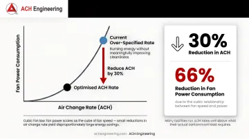
- Reducing ACH by 30% can cut fan power by 66%, according to a ResearchGate study on cleanroom energy use — proper design balances filtration efficiency with energy consumption
- Demand-controlled filtration tied to real-time occupancy can reduce fan energy by up to 93.6% in low-occupancy labs and research facilities
Understanding Cleanroom HVAC Systems
Cleanroom HVAC systems serve four fundamental objectives that distinguish them from conventional environmental control:
Primary Control Objectives:
- Airborne particle control - Maintaining particle concentrations within ISO 14644-1 limits
- Temperature/humidity regulation - Typically 68°F ±2°F and 30-60% RH ±5%
- Pressurization management - Creating cascading pressure differentials (0.02-0.05 in. w.c.) between zones
- Cross-contamination prevention - Ensuring unidirectional flow from clean to less clean areas
System Differentiation from Conventional HVAC
The performance gap between cleanroom and commercial systems is quantifiable:
| Parameter | Commercial HVAC | Cleanroom HVAC |
|---|---|---|
| Air Changes per Hour | 1-2 ACH | 10-600 ACH |
| Filtration Efficiency | MERV 8-13 | HEPA 99.97%+ |
| Energy Intensity | ~0.06 kW/m² | Up to 1.52 kW/m² |
| Pressure Control | Minimal | Precise cascading differentials |
These numbers reflect three performance parameters that every cleanroom HVAC design must address:
Critical Performance Parameters
- Air cleanliness — Particle concentration limits defined by ISO 14644-1 classification, measured at sizes from 0.1 µm to 5.0 µm depending on the class.
- Air change rate (ACH) — The number of times per hour the total room volume cycles through filtered air. Calculated as: ACH = (Airflow in CFM × 60) ÷ Room Volume (ft³). See Cleanroom Technology's ACH calculation reference for worked examples.
- Room pressurization — Positive pressure relative to adjacent spaces, typically 0.02–0.05 in. w.c. (5–12.5 Pa), blocks contaminant infiltration. Leakage follows a power law (Q = C ΔP^n), per AIVC pressure-leakage research, meaning even small envelope gaps significantly increase makeup air demand.
Understanding these parameters clarifies why cleanroom systems manage two separate airflow streams rather than treating all supply air the same way.
Makeup Air vs. Recirculated Air
- Makeup Air Units (MAU) condition 100% outdoor air to handle pressurization, exhaust replacement, and latent (humidity) loads. Typical makeup air volume equals total exhaust plus approximately 2 ACH for envelope leakage.
- Recirculation Air Handling (RAH) processes the bulk of airflow through HEPA filters to sustain ACH requirements and remove sensible heat from equipment and personnel.
Separating these streams is the primary energy conservation lever in cleanroom design. Each unit handles only what it's sized for — the MAU manages outdoor air conditioning, the RAH handles recirculation — rather than over-conditioning every cubic foot of supply air to full outdoor air standards.
Cleanroom Classification and ACH Requirements
ISO 14644-1 Classification Standards
The ISO 14644-1:2015 standard defines cleanroom classes based on maximum allowable particle concentrations at specified particle sizes:
| ISO Class | Max Particles/m³ ≥0.5 µm | Max Particles/m³ ≥1.0 µm | Max Particles/m³ ≥5.0 µm | Fed Std 209E Equivalent |
|---|---|---|---|---|
| ISO 3 | 35 | - | - | Class 1 |
| ISO 4 | 352 | 83 | - | Class 10 |
| ISO 5 | 3,520 | 832 | - | Class 100 |
| ISO 6 | 35,200 | 8,320 | 293 | Class 1,000 |
| ISO 7 | 352,000 | 83,200 | 2,930 | Class 10,000 |
| ISO 8 | 3,520,000 | 832,000 | 29,300 | Class 100,000 |
Industry-Standard ACH Ranges
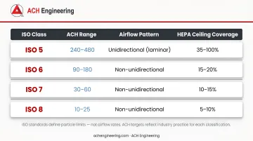
ISO standards define particle limits — not airflow rates. Once you know your required classification, industry practice translates those limits into ACH targets like these:
| ISO Class | ACH Range | Airflow Pattern | HEPA Ceiling Coverage |
|---|---|---|---|
| ISO 5 | 240-480 | Unidirectional (laminar) | 35-100% |
| ISO 6 | 90-180 | Non-unidirectional | 15-20% |
| ISO 7 | 30-60 | Non-unidirectional | 10-15% |
| ISO 8 | 10-25 | Non-unidirectional | 5-10% |
Calculating Required Airflow
Formula: CFM = (Room Volume in ft³ × ACH) / 60
Example Calculation:
- Room dimensions: 20 ft × 15 ft × 10 ft = 3,000 ft³
- ISO 7 requirement: 40 ACH (mid-range)
- Required airflow: (3,000 × 40) / 60 = 2,000 CFM
Face Velocity vs. ACH Specifications
For ISO 5 and cleaner environments requiring unidirectional flow, engineers and designers typically specify face velocity rather than ACH:
- Standard face velocity: 90 FPM ±20% (0.36-0.54 m/s)
- Calculation: CFM = Filter Area (ft²) × Face Velocity (FPM)
When to use each approach:
- Use ACH for non-unidirectional cleanrooms (ISO 6–8), where dilution ventilation controls particle concentration
- Use face velocity for unidirectional cleanrooms (ISO 5 and below), where laminar displacement physically sweeps particles away
Key HVAC System Components
HEPA and ULPA Filter Specifications
HEPA filters are the primary line of defense for cleanroom air quality. The Department of Energy defines HEPA performance as a minimum 99.97% efficiency at 0.3 micrometers—the Most Penetrating Particle Size (MPPS).
Performance characteristics:
- Efficiency: 99.97% minimum at 0.3 µm (H13: 99.95%, H14: 99.995%)
- Initial pressure drop: 1.0-1.3 in. w.c. (250-325 Pa)
- Replacement threshold: 2.0-4.0 in. w.c. (approximately double initial resistance)
- Face velocity: 90 FPM nominal for unidirectional applications
ULPA filters step in for ISO 3-4 applications where HEPA filtration falls short:
- Efficiency: 99.999%+ at 0.12 µm
- Higher pressure drop and cost than HEPA
- Reserved for the most particle-sensitive environments
Pre-Filtration Systems
Protecting expensive terminal HEPA filters requires robust pre-filtration. ASHRAE recommends MERV 13 minimum, with MERV 14-16 preferred for extending HEPA service life. Pre-filters capture larger particles before they reach HEPA media, reducing loading rates and replacement frequency.
This pre-filtration stage feeds directly into the makeup air system, which handles all incoming outdoor air.
Makeup Air Handling Units (MAU)
MAUs condition 100% outdoor air to meet three critical functions:
- Pressurization maintenance - Supplying air to offset exhaust and leakage
- Latent load control - Dehumidification to maintain 30-60% RH
- Initial filtration - Pre-filtering outdoor air before introduction
Sizing considerations:
- Calculate total exhaust volume
- Add 2 ACH for envelope leakage (adjust based on building tightness)
- Design for high static pressure capability (up to 4 in. w.c.)
Once makeup air is conditioned and introduced, recirculation units take over to maintain the continuous high-volume airflow cleanrooms require.
Recirculation Air Handling Units (RAH)
RAH units process the bulk of cleanroom airflow, handling sensible cooling loads and maintaining ACH requirements.
Fan selection criteria:
- Centrifugal fans: higher static pressure capability, better suited for ducted systems
- Vane-axial fans: lower pressure drop, suitable for short duct runs
- Variable Frequency Drives (VFDs): fan power scales with speed cubed, so even modest flow reductions produce significant energy savings
Fan Filter Units (FFU)
FFUs are self-contained modules combining fan and HEPA filter, installed directly in ceiling grids.
Advantages:
- Lower capital cost than centralized systems
- Redundancy—single unit failure doesn't compromise entire room
- Easy classification upgrades by adding units
- Simplified distribution—no ductwork required
Disadvantages:
- Higher noise levels from multiple motors
- Maintenance complexity with numerous units
- Individual filter monitoring more challenging
Ductwork Design Requirements
Material selection:
- Aluminum or stainless steel preferred for cleanability
- Galvanized steel acceptable for pre-filtered supply
Critical specifications:
- Maximum velocity: 1,500-2,000 FPM to minimize noise and pressure loss
- Sealed construction with gaskets at all joints
- Access doors every 20-30 feet for cleaning
- Internal insulation avoided (external only) to prevent particle generation
Airflow Patterns and Distribution Strategies
Cleanroom airflow design falls into two fundamental approaches — unidirectional and non-unidirectional — each suited to specific ISO classifications. Return air strategy ties directly to whichever flow type you select.
Unidirectional (Laminar) Flow
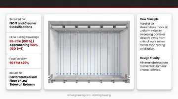
Required for: ISO 5 and cleaner classifications
Unidirectional flow creates parallel air streamlines moving at uniform velocity (vertical), sweeping particles directly away from critical work zones rather than relying on dilution.
Design requirements:
- HEPA ceiling coverage: 35-70% for ISO 5, approaching 100% for ISO 3-4
- Face velocity: 90 FPM ±20%
- Return air: Perforated raised floor or low sidewall returns
- Minimal obstructions to maintain laminar characteristics
Non-Unidirectional (Turbulent) Flow
Used for: ISO 6-8 classifications
This approach relies on mixing filtered supply air with room air to dilute particle concentrations to acceptable levels. Equipment and furniture placement is more forgiving, making it a practical choice for general-purpose cleanrooms.
Key design parameters:
- HEPA ceiling coverage: 5-20% depending on class
- Supply diffusers promote mixing
- Return air: Low sidewall returns recommended
- More tolerant of equipment and furniture placement
Return Air Strategies
The return air configuration you choose reinforces — or undermines — your selected flow pattern. Each option carries specific placement rules and cost implications.
Low Sidewall Returns:
- Promote vertical air movement and mixing
- Prevent short-circuiting of supply air
- Suitable for room widths up to 20-25 feet
- Most common for non-unidirectional designs
Raised Floor Returns:
- Required for unidirectional flow rooms
- Perforated floor panels (25% open area)
- Maintains downward laminar flow
- Adds significant construction cost
Mixed-Flow Approaches: For facilities with multiple cleanliness zones, establish contamination barriers through:
- Pressure cascades (higher pressure in cleaner zones)
- Physical separation with airlocks
- Directional airflow from clean to less clean areas
Pressurization and Environmental Control
Cascading Pressure Differentials
Maintaining positive pressure prevents contaminant infiltration and creates directional airflow from clean to less clean spaces.
Standard differential: 0.02–0.05 in. w.c. (5–12.5 Pa) between adjacent zones
Example pressure cascade:
- ISO 5 Core: +0.10 in. w.c. (relative to ambient)
- ISO 7 Support: +0.05 in. w.c.
- Gowning Area: +0.02 in. w.c.
- Corridor: 0.00 in. w.c. (ambient reference)
EU GMP Annex 1 specifically recommends 10 Pascals between zones of different grades in pharmaceutical applications.
Makeup Air Calculation for Pressurization
Basic formula: Makeup Air CFM = Exhaust CFM + Leakage CFM
Leakage estimation commonly uses 2 ACH as a starting point, but actual values depend on envelope construction quality. The relationship is non-linear, following Q = C ΔP^n, where n typically ranges from 0.5 to 1.0.
Watch for over-pressurization: doubling pressure from 0.03 to 0.06 in. w.c. doesn't double leakage — it raises it by roughly 40–70%, wasting conditioned air and energy without proportional benefit.
Temperature and Humidity Control
Temperature setpoints:
- Standard: 20°C (68°F) or lower
- Tolerance: ±2°F typical
- Driven by personnel comfort in gowning, not process (in most applications)
Humidity control:
- Optimal range: 30–60% RH
- Tighter pharmaceutical spec: 45–50% RH ±5%
- Below 30%: Increased static electricity risk
- Above 60%: Microbial growth promotion
Effective control separates sensible (temperature) and latent (humidity) loads. Makeup air units (MAUs) handle dehumidification of outdoor air, while recirculating air handlers (RAHs) manage sensible cooling from internal gains.
Common HVAC Design Mistakes and Solutions
Over-Specification of Air Change Rates
Many facilities run ACH rates well above what their actual contaminant load requires — burning energy without meaningfully improving cleanliness. Reducing ACH by 30% can cut fan power consumption by approximately 66% due to the cubic relationship between fan speed and power.
Many facilities run ACH rates well above what their actual contaminant load requires — burning energy without meaningfully improving cleanliness. Reducing ACH by 30% can cut fan power consumption by approximately 66% due to the cubic relationship between fan speed and power.
To right-size your ACH:
- Run particle generation studies to establish actual contamination rates before setting targets
- Install Variable Frequency Drives (VFDs) so airflow can be adjusted without hardware changes
- Use occupancy-based controls to reduce ACH during unoccupied periods
- Evaluate demand-controlled filtration driven by real-time particle counts — this approach has delivered fan energy savings up to 93.6% in pharmaceutical facilities
Improper Filter Selection, Placement, or Sealing
Filter bypass — caused by poor sealing, wrong filter specification, or insufficient pre-filtration — is one of the more quietly damaging failures in cleanroom HVAC. The room can appear to pass classification testing while contaminated air routes around filters undetected.
Key installation and testing requirements:
- All terminal HEPA filters must be DOP (Dispersed Oil Particulate) / PAO (Poly-Alpha Olefin) tested after installation
- Leak scanning required every 12 months; every 6 months for ISO 5 and cleaner environments
- MERV 13+ pre-filtration is essential to protect HEPA service life
- Use gel-seal or knife-edge frames — gasket-only seals are not adequate
For testing protocol, follow NEBB (National Environmental Balancing Bureau) Procedural Standards and IEST-RP-CC034 for aerosol photometer methods.
Inadequate Makeup Air Calculations
An undersized makeup air unit (MAU) creates cascading pressure problems — doors become difficult to operate, pressure differentials fluctuate with every opening, and contamination can infiltrate during transitions.
Watch for these warning signs in existing or commissioning systems:
- Doors are hard to open due to excessive pressure differential
- Pressure readings spike or drop when doors open
- Target differentials cannot be held consistently
- Infiltration is visible or measurable during door cycles
When sizing the MAU, start with "exhaust + 2 ACH" as a baseline and refine against envelope testing results. Build in 20–30% capacity margin, install continuous pressure monitoring with alarms, and evaluate vestibules or airlocks at boundaries where contamination risk is highest.
Frequently Asked Questions
What is a cleanroom in HVAC context?
A cleanroom is an enclosed space where HVAC systems control airborne particle concentration, temperature, humidity, and pressure to meet specific ISO 14644-1 cleanliness classifications.
What are the requirements for ISO 7 HVAC?
ISO 7 cleanrooms require maximum 352,000 particles/m³ at 0.5 µm, 30-60 air changes per hour, non-unidirectional airflow with 10-15% HEPA ceiling coverage, and positive pressurization of 0.02-0.05 in. w.c. relative to adjacent spaces.
What is a cleanroom makeup air unit?
A makeup air unit is dedicated HVAC equipment that conditions outside air (temperature, humidity, and filtration) to replace exhausted air and maintain room pressurization. It handles both sensible and latent loads from outdoor air independently of recirculation systems.
How do you calculate air changes per hour for a cleanroom?
Use the formula: ACH = (Airflow in CFM × 60) / Room Volume in cubic feet. To determine required CFM, multiply room volume by the target ACH for your ISO class, then divide by 60.
What is the difference between HEPA and ULPA filters in cleanroom applications?
HEPA filters capture 99.97% of particles at 0.3 µm and suffice for ISO 5-8 applications. ULPA filters achieve 99.999% efficiency at 0.12 µm, required for ISO 3-4 environments. ULPA filters cost more and create higher pressure drop.
Can cleanroom HVAC systems be energy efficient?
Yes. Strategies include optimized ACH rates based on actual contamination generation, variable speed drives on fans, demand-controlled filtration based on occupancy or particle counts, and low-pressure drop filter designs. According to a peer-reviewed energy analysis in Building and Environment, these approaches can reduce energy consumption by 30-50% without compromising cleanliness standards.
Need expert cleanroom HVAC design for your facility? ACH Engineering provides cleanroom design, manufacturing, and construction services for pharmaceutical, biotech, medical device, and other regulated industries throughout North America. Our team holds credentials including PEO (Professional Engineers Ontario), ISPE (International Society for Pharmaceutical Engineering), and PMI (Project Management Institute) — ensuring your cleanroom HVAC systems meet ISO 14644-1 standards and industry-specific regulatory requirements. Contact our technical team at sales@achengineering.com or +1 647-406-5721 for a project consultation.