Introduction
Low wall return air systems require precise engineering to balance airflow patterns, pressure differentials, and contamination control. Improper design leads to classification failures, energy waste, and compromised product safety—consequences that derail pharmaceutical production, invalidate sterile compounding environments, or cause costly facility shutdowns.
The stakes are particularly high in regulated industries. FDA guidance explicitly requires low wall return placement for aseptic processing, while USP <797> and <800> mandate these systems for pharmaceutical compounding spaces.
Yet many facilities still experience pressure cascade failures, turbulent airflow zones, and particle count excursions due to fundamental design errors made during the planning phase.
Successful low wall return air system design demands cross-disciplinary collaboration:
- HVAC engineers calculate airflow volumes and pressure drops
- Cleanroom consultants apply contamination control principles
- Facility planners coordinate spatial constraints and equipment placement
- Compliance specialists ensure designs meet ISO 14644, FDA, and USP standards
When these disciplines work in isolation, the result is often undersized return grills, improper placement that disrupts laminar flow, or inadequate pressure differential planning that allows cross-contamination between zones.
Key Takeaways
- Low wall returns capture descending particles at floor level, maintaining ISO 5-7 cleanroom standards
- Position grills 6-12 inches above floor with 200-400 FPM face velocity
- Design must maintain 0.02-0.05 inches water column pressure differentials between adjacent cleanroom zones
- Low wall returns reduce particle concentrations by 12-33% vs. high-level systems
- Avoid undersized capacity, improper placement, and skipping CFD validation
Understanding Low Wall Return Air Systems
What Low Wall Return Air Systems Are
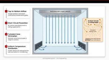
A low wall return air system positions air exhaust grills near the floor—typically 6-12 inches above the finished floor—to capture descending air and particles. This configuration completes the unidirectional airflow pattern established by ceiling-mounted HEPA supply diffusers, creating a "piston effect" that continuously sweeps contaminants downward and removes them from the cleanroom environment.
Particles generated by personnel, processes, and equipment naturally settle due to gravity. By positioning return grills at low levels, the system captures these particles before they can recirculate into the breathing zone or critical work areas.
The Role in Cleanroom Airflow
Low wall returns are essential for achieving true unidirectional (laminar) airflow in controlled environments. Without them, air short-circuits directly back to ceiling supply points.
This creates turbulent mixing patterns and leaves particles suspended in the space.
The system works by:
- Establishing top-to-bottom airflow that sweeps particles downward continuously
- Preventing turbulent zones where particles can accumulate
- Maintaining uniform temperature distribution by capturing cooler, heavier air that settles at floor level
- Supporting pressure cascade requirements between adjacent cleanroom zones
Low Wall Returns vs. High-Level Returns
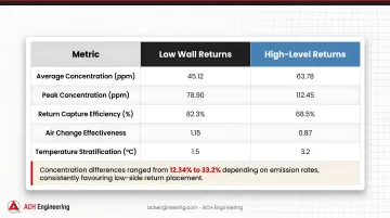
Research comparing return air placement shows significant performance differences. Low-side returns consistently maintained lower particle concentrations than high-side returns, with concentration differences ranging from 12.34% to 33.2% depending on emission rates.
Performance Comparison:
| Metric | Low Wall Returns | High-Level Returns | Impact |
|---|---|---|---|
| Particle concentration | Baseline | +12.34% to +33.2% higher | Significantly worse contamination control |
| Air distribution uniformity | Non-uniformity coefficient: 0.45-0.53 | Non-uniformity coefficient: 0.50-0.67 | 11.9% worse uniformity with high returns |
| Temperature stratification | Uniform distribution | Poor stratification | High returns allow thermal layering |
High-level returns create turbulent mixing patterns because they pull air upward against the natural settling direction of particles, reducing removal efficiency and creating dead zones where contamination accumulates.
Essential Applications
Low wall return air systems are mandated or strongly recommended for:
Pharmaceutical and Biotech:
- ISO Class 5-7 cleanrooms for aseptic processing
- USP <797> sterile compounding buffer rooms and anterooms (minimum 30 ACH required)
- USP <800> hazardous drug compounding areas
- FDA-regulated sterile manufacturing facilities
Other Critical Industries:
- Semiconductor fabrication facilities where particle contamination affects yield
- Medical device manufacturing requiring sterile assembly conditions
- Aerospace component production with stringent cleanliness requirements
- Research laboratories handling sensitive biological materials
Impact on Cleanroom Classification
Proper low wall return design directly influences the ability to achieve and maintain ISO classification. The system's effectiveness in removing particles determines whether a space can consistently meet particle count limits during operational conditions.
For ISO Class 5 environments (maximum 3,520 particles ≥0.5 microns per cubic meter), low wall returns are essential to maintain the unidirectional airflow at 90±20 feet per minute required by the standard. Without effective low-level return capture, even spaces with 100% HEPA ceiling coverage will experience particle count excursions during operations.
Design Fundamentals and Requirements
Air Change Rates and Volumetric Requirements
ISO 14644-1 establishes particle concentration limits but does not specify air change rates (ACH). Designers must reference industry guidelines to determine appropriate ACH for achieving target classifications.
Industry-Standard ACH Requirements:
| ISO Class | Application | Required ACH | Notes |
|---|---|---|---|
| ISO 5 | Aseptic processing critical zones | 200-600 ACH | Requires unidirectional flow with high velocity coverage |
| ISO 7 | USP <797> buffer/anteroom | ≥30 ACH | Minimum regulatory requirement |
| ISO 7 | EU Grade B pharmaceutical | 40-60 ACH | Typical design range |
| ISO 8 | USP <797> support rooms | ≥20 ACH | Minimum for classified spaces |
| ISO 8 | EU Grade C pharmaceutical | 20-40 ACH | Standard design range |
To calculate required return air capacity, first determine total supply CFM based on room volume and target ACH:
Supply CFM = (Room Volume in cubic feet × ACH) ÷ 60 minutes
Return air volume typically equals 85-95% of supply CFM for positive pressure rooms. The difference is exhausted to maintain the required pressure differential.
Return Air Grill Sizing Methodology
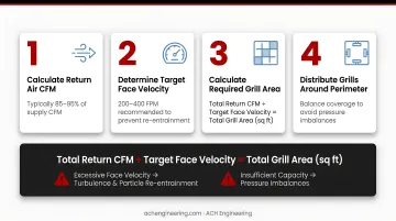
Proper grill sizing prevents two critical problems: excessive face velocity that causes turbulence and particle re-entrainment, and insufficient capacity that creates pressure imbalances.
Sizing Process:
- Calculate total return air CFM (typically 85-95% of supply CFM)
- Determine target face velocity (200-400 FPM recommended to prevent re-entrainment)
- Calculate required grill area: Total Return CFM ÷ Target Face Velocity = Total Grill Area (square feet)
- Distribute grills around perimeter to achieve even airflow distribution
Example Calculation:
- Room requires 2,000 CFM supply for ISO 7 classification
- Return air volume: 1,900 CFM (95% of supply)
- Target face velocity: 300 FPM
- Required grill area: 1,900 ÷ 300 = 6.33 square feet
- Using 18" × 18" grills (2.25 sq ft each): Need 3 grills minimum
Industry best practices recommend inlet velocities at return grills between 300-400 FPM, with velocities gradually increasing to 1,200-1,800 FPM in return air risers to effectively transport particulate matter.
Placement Specifications
Once grills are sized, strategic placement becomes critical for maintaining unidirectional flow and avoiding dead zones.
Height Requirements:
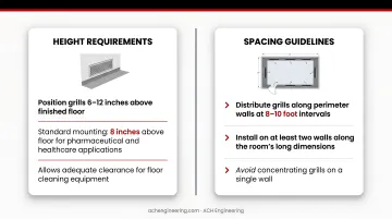
- Position grills 6-12 inches above finished floor
- Standard mounting: 8 inches above floor for pharmaceutical and healthcare applications
- Allows adequate clearance for floor cleaning equipment
Spacing Guidelines:
- Distribute grills along perimeter walls at 8-10 foot intervals
- Install on at least two walls along the room's long dimensions
- Avoid concentrating returns in corners, which creates uneven airflow
Positioning Relative to Equipment:
- Maintain clearance behind process equipment to allow air to flow to returns
- Position returns near contamination sources (e.g., adjacent to sinks in anterooms)
- Avoid placement directly below supply air, which causes short-circuiting
Pressure Differential Considerations
Maintaining precise pressure cascades prevents cross-contamination between cleanroom zones and protects critical areas from unclassified spaces.
Required Pressure Differentials:
- FDA guidance: 10-15 Pascals (0.04-0.06 inches water column) between adjacent rooms
- USP <797>: Minimum 0.02 inches water column between classified spaces
- USP <800> (hazardous drugs): Negative pressure of 0.01-0.03 inches water column for containment areas
- EMA Annex 1: Minimum 10 Pascals between different grade rooms
Return air system design must account for pressure drops through the entire return path, including grills, ductwork, and dampers. Undersized return capacity creates pressure "bottlenecks" that disrupt cascades and can reverse airflow direction.
Filtration Integration
Supply air requires HEPA filtration (99.97% efficiency at 0.3 microns). Return air filtration serves a different purpose: protecting HVAC equipment and enabling recirculation.
Return Air Filtration Requirements:
- Minimum MERV 14 filters upstream of air handling units (ASHRAE recommendation)
- MERV 8-14 filters protect ductwork and equipment from contamination
- For hazardous drug applications (USP <800>), return air must be independent of general HVAC return
- Risk assessment required before implementing recirculation in volatile compound environments
Compliance Requirements
Design must address multiple overlapping standards:
ISO 14644-4: Establishes design and construction requirements for cleanroom facilities, including airflow patterns and filtration specifications
FDA Guidance for Aseptic Processing: Requires air supplied from ceiling and returned via low wall locations to protect sterile materials
USP <797>: Mandates low wall returns for sterile compounding buffer rooms and anterooms, with specific ACH minimums
USP <800>: Requires low wall returns for hazardous drug compounding areas with negative pressure requirements
Industry-Specific Standards: Semiconductor, aerospace, and medical device industries have additional requirements based on product sensitivity
Design Process for Low Wall Return Systems
A systematic design process ensures all technical, regulatory, and operational requirements are met before construction begins, preventing costly modifications during commissioning.
Define Cleanroom Classification and Application Requirements
Establish the foundation that drives all subsequent design parameters:
- Target ISO classification (5, 6, 7, or 8)
- Regulatory compliance needs (FDA, USP <797>/<800>, GMP)
- Process requirements and product sensitivity
- Operational conditions (personnel density, equipment heat loads, particle generation rates)
This step determines minimum ACH, filtration levels, pressure relationships, and whether unidirectional flow is required.
Calculate Airflow and Air Change Requirements
Follow this calculation sequence:
- Determine required ACH based on classification and regulatory requirements
- Calculate room volume (length × width × ceiling height in feet)
- Calculate total supply CFM: (Volume × ACH) ÷ 60 minutes
- Determine return air volume: Typically 85-95% of supply CFM for positive pressure rooms
- Calculate exhaust volume: Supply CFM - Return CFM = Exhaust CFM (maintains pressure differential)
Example for ISO 7 Buffer Room:
- Room dimensions: 12 ft × 10 ft × 9 ft ceiling = 1,080 cubic feet
- Required ACH: 30 minimum (USP <797>)
- Supply CFM: (1,080 × 30) ÷ 60 = 540 CFM
- Return CFM: 513 CFM (95% of supply)
- Exhaust CFM: 27 CFM (maintains positive pressure)
Develop Room Layout and Return Air Placement Strategy
With airflow requirements established, translate those numbers into spatial planning. Position return grills to optimize unidirectional flow while accounting for physical constraints:
- Distribute grills evenly along perimeter walls (typically two or three walls)
- Maintain 8-10 foot maximum spacing between grills
- Position near contamination sources (sinks, refrigerators, personnel entry)
- Avoid placement behind equipment that blocks airflow
- Keep clear of door swing paths and traffic patterns
- Ensure accessibility for filter changes and maintenance
To prevent dead zones where air stagnates, use CFD modeling to identify areas with inadequate circulation. Add grills in corners or alcoves, and account for room geometry and equipment placement that may disrupt flow.
Size and Specify Return Air Components
Calculate individual grill sizes based on total return CFM and target face velocity (200-400 FPM). Select grill types—perforated, louvered, or flush-mounted—based on cleanability and aesthetic requirements. Specify materials: typically stainless steel or powder-coated steel for GMP compliance.
Size return ducts to maintain appropriate velocity (typically 1,200-1,800 FPM in risers), accounting for pressure drop through duct runs, fittings, and dampers. Ensure adequate capacity to prevent pressure bottlenecks.
For filtration, specify MERV 8-14 filters for return air based on application. Determine filter access locations for maintenance and calculate filter pressure drop and replacement frequency.
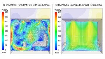
Model and Validate Design Using CFD Analysis
Computational Fluid Dynamics (CFD) modeling is essential for validating airflow patterns before construction. CFD identifies potential problems that are impossible to detect from drawings alone.
CFD analysis validates:
- Verify unidirectional flow patterns throughout the space
- Identify turbulence zones and dead spots where particles accumulate
- Validate that recovery times meet regulatory targets (typically 15-20 minutes)
- Optimize return grill placement to eliminate high-risk contamination zones
- Confirm pressure differentials between adjacent spaces
In one pharmaceutical facility design, initial return placement created high-risk contamination zones. CFD modeling identified the problem before construction, allowing the design team to redistribute returns along additional walls.
The revised design eliminated dead zones and reduced predicted recovery time from 28 minutes to 16 minutes, ensuring compliance with regulatory requirements.
ACH Engineering provides CFD services for design validation, helping clients identify and correct airflow issues during the planning phase—before construction when modifications become significantly more expensive.
Common Design Mistakes and Solutions
Learning from common design errors prevents costly redesigns and commissioning failures. These mistakes compromise cleanroom performance and create ongoing operational issues.
Undersized Return Air Capacity
Problem: Return grills sized too small for required airflow volume cause high face velocities. This creates turbulence and pulls settled particles back into the cleanroom environment.
Likely Causes:
- Using rules of thumb instead of actual calculations based on supply CFM
- Attempting to minimize visible grills for aesthetic reasons
- Failing to account for actual air change requirements for the classification
- Not considering pressure drop through the entire return path
Solution:
- Calculate return air CFM based on supply volume (typically 85-95% of supply)
- Size grills for 200-400 FPM face velocity maximum
- Distribute capacity across sufficient wall area rather than concentrating in fewer grills
- Account for pressure drop through grills, ductwork, and filters when sizing
These sizing principles matter in practice. One cleanroom suite experienced pressure cascade failures due to a single 18" × 18" return grille handling 2,205 CFM, resulting in a face velocity of 978 FPM (more than double the recommended maximum).
This created a pressure bottleneck that disrupted the entire facility's pressure relationships. Adding two additional grills immediately resolved the pressure issues.
Improper Return Grill Placement
Problem: Returns positioned too high on walls, too close to supply air, or concentrated in corners disrupt laminar flow patterns and create dead zones where contamination accumulates.
Likely Causes:
- Architectural constraints taking priority over airflow requirements
- Lack of CFD modeling during design phase
- Poor coordination between architectural, HVAC, and process design teams
- Insufficient understanding of unidirectional flow principles
Solution:
- Position returns 6-12 inches above finished floor (typically 8 inches)
- Distribute evenly along perimeter walls with 8-10 foot maximum spacing
- Install on at least two walls along the room's long dimensions
- Avoid placement directly below supply air, which causes short-circuiting
- Maintain clearance behind equipment so air can flow to returns
- Use CFD modeling to validate placement before construction
Common Placement Errors:
- Concentrating all returns on one wall, creating uneven flow
- Placing returns in corners only, leaving center areas with poor circulation
- Installing returns too high (above 18 inches), reducing effectiveness
- Blocking returns with equipment, shelving, or process fixtures
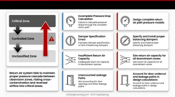
Inadequate Pressure Differential Planning
Problem: Return air system doesn't maintain proper pressure cascade between cleanroom zones. This causes cross-contamination or reversed airflow that allows unclassified air to enter critical areas.
Likely Causes:
- Failure to calculate pressure drops through the complete return path
- Improper damper specification or lack of balancing dampers
- Inadequate return air capacity in downstream spaces
- Not accounting for door openings and other leakage paths
Solution approaches include:
- Design return air system to maintain 0.02-0.05 inches water column differential between adjacent zones
- Calculate pressure drop through grills, ductwork, filters, and dampers
- Specify proper balancing dampers with position indicators
- Ensure return duct sizing accounts for total system pressure drop
- Install continuous pressure monitoring with alarms as required by regulations
- Plan for adequate makeup air to replace exhausted air
Critical Design Considerations:
Each zone must have sufficient return capacity to maintain its target pressure. The pressure cascade must flow from most critical (highest pressure) to least critical (lowest pressure).
For hazardous drug areas (USP <800>), negative pressure requires exhaust volume to exceed supply volume.
Best Practices for Effective Design
Integrate Return Air Planning Early in Modular Cleanroom Panel Design
For modular cleanroom construction, specify panels with integrated return air plenums and pre-positioned grill openings during the design phase.
This approach simplifies installation, ensures proper placement, and avoids field modifications that compromise panel integrity.
Benefits of Integrated Design:
- Eliminates field cutting of panels that can damage finishes and seals
- Ensures return openings align with structural framing and ductwork
- Maintains GMP-compliant smooth surfaces and coved corners
- Reduces installation time and coordination errors
These integrated design features prove especially valuable in pharmaceutical and biotech applications where cleanroom integrity is non-negotiable.
ACH Engineering's modular cleanroom solutions incorporate return air design features directly into panel specifications, ensuring seamless integration between architectural and HVAC systems.
Design for Maintenance Accessibility
Position return grills and filters for easy access without disrupting cleanroom operations or compromising classification during maintenance activities.
Accessibility Strategies:
- Return grills should be positioned away from fixed equipment and process areas
- Specify removable panels for ductwork inspection and filter changes
- Minimum 24 inches of clearance in front of grills enables proper filter access
- Design filter access from outside the cleanroom when possible
- Quick-release fasteners simplify maintenance compared to permanent attachments
- Document filter locations and replacement procedures in O&M manuals
Maintenance Planning:
- Schedule filter changes based on pressure drop monitoring, not arbitrary timelines
- Keep replacement filters stocked on-site to minimize downtime
- Train facility staff on proper filter handling to prevent contamination
Plan for Future Flexibility
Design return air capacity with 15-20% margin for potential classification upgrades, process changes, or equipment additions. This buffer prevents the need for major HVAC modifications when operational requirements evolve.
Flexibility Strategies:
- Return ductwork should be sized for higher CFM than initially required
- Install capped stub-outs for future return grill locations
- Modular duct systems allow easy reconfiguration as needs change
- Specify air handling units with capacity for increased airflow
- Electrical and control systems need capacity for additional zones
Future-Proofing Considerations:
- Pharmaceutical facilities may need to upgrade from ISO 8 to ISO 7 classification
- Changes in manufacturing processes can demand higher air change rates
- Equipment additions increase heat loads and particle generation
- Regulatory requirements may become more stringent over time
Frequently Asked Questions
What is a low wall return in a cleanroom?
A low wall return is an air exhaust grill positioned near the floor, typically 6-12 inches above the finished floor, that captures descending air and particles. This configuration enables unidirectional top-to-bottom airflow essential for maintaining cleanroom classification by continuously sweeping contaminants downward and removing them from the space.
What are the guidelines for a cleanroom?
Primary guidelines include ISO 14644 for classification and design, FDA guidance for pharmaceutical applications, and USP <797>/<800> for sterile compounding. These establish requirements for airflow patterns, filtration, pressure differentials, and materials selection.
What are the ISO 5 cleanroom standards?
ISO 5 (formerly Class 100) allows maximum 3,520 particles ≥0.5 microns per cubic meter and requires unidirectional airflow at 90±20 feet per minute with 100% HEPA ceiling coverage. Low wall returns maintain the laminar flow pattern essential for this classification.
What are the requirements for a Class 100,000 cleanroom?
Class 100,000 (ISO 8) allows maximum 3,520,000 particles ≥0.5 microns per cubic meter and requires 10-15 air changes per hour. It uses turbulent or mixed airflow patterns, and while low wall returns improve performance, high-level returns may be acceptable.
How do you calculate the number and size of low wall return grills needed?
First calculate total return air CFM (typically 85-95% of supply CFM), then divide by target face velocity (200-400 FPM) to determine total required grill area in square feet. Finally, distribute grills around the perimeter to achieve even airflow distribution, typically spacing them 8-10 feet apart on at least two walls.
Can low wall return systems be retrofitted into existing cleanrooms?
Retrofits are possible but require assessing existing HVAC capacity, evaluating wall construction for grill installation, and considering operational disruption. Surface-mounted return assemblies offer alternatives when wall penetrations aren't feasible.